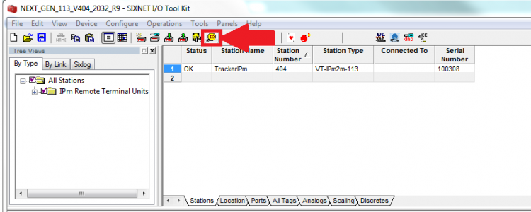
Start Procedure - Click Arrow >
WARNING
NOTE
NOTE
The following screenshots are for instructional purposes only. The values found in the I/O transfers in these photos are not from a working unit, and likely will not match the values seen on a working tracker.
To change the I/O values, simply click the corresponding box in the I/O value section, type the desired value, and press enter.
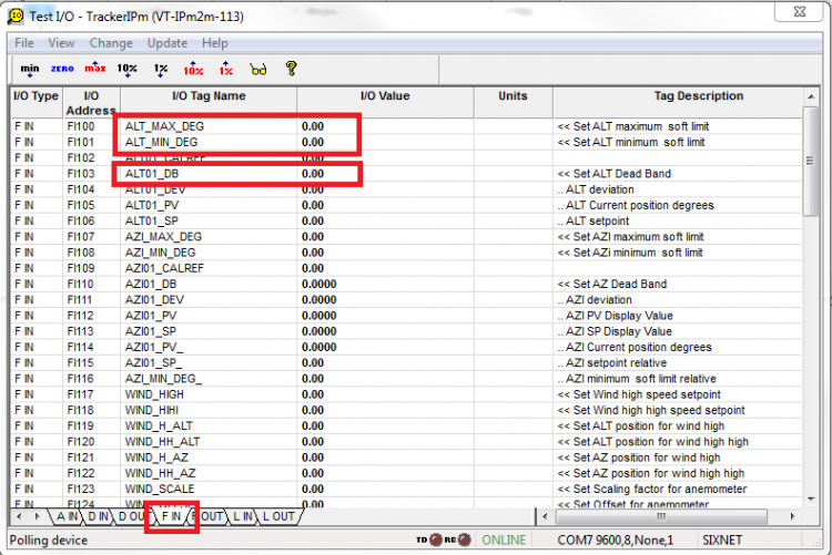
Configuration for Altitude Motor.
I/O Test
- ALT_MAX_DEG defines the soft limit max for altitude adjustment, which imposes an upper limit on the motor movement for the altitude motor
- ALT_MIN_DEG defines the soft limit minimum for altitude adjustment, which imposes a lower limit on the motor movement for the altitude motor
- ALT01_DB defines the dead band for the altitude motor control. Smaller dead band will adjust the motor position more often, and increase accuracy, but can also cause unnecessary wear on the motor.
Altitude I/O Values
Scroll down to the following tags (FI133, FI137, FI141, and FI145)
- ALT01_TC changes the time constant for the altitude motor
- ALT01_STOW changes the altitude night stow position for the panel. A stow position of zero will cause the motor to remain in its last position at night. Any other degree input will cause the motor to stow at night in that position.
Altitude I/O Values (continued)
- ALT01_CORRECTION allows the user to apply a correction to the altitude position of the motor. If the tracker appears to be off from the sun, this can be used to correct it.
- ALT01_ZERO is the angle of the physical altitude limit switch. When the tracker hits the limit switch it will use this value to re-calibrate its present position.
Altitude Limit Switches
Next go back to the A IN tab and locate the following I/O transfers (AX140 and AX141)
- ALT01_ZMIN_CONF configures the minimum limit switch. Input 0 for normally open, 16 to reverse to normally closed, and 86 to disable
- ALT01_ZMAX_CONF configures the maximum limit switch. Input 0 for normally open, 16 to reverse to normally closed, and 86 to disable
Pulses
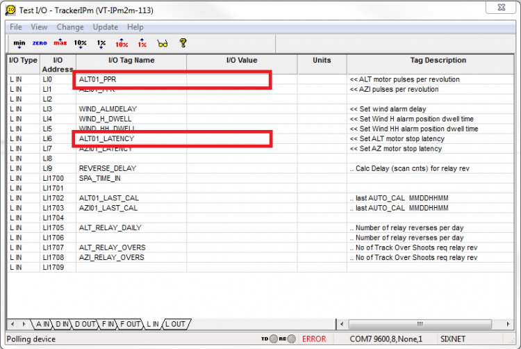
Now switch to the L OUT tab and locate the transfers squared in red
ALT01_PPR defines the number of pulses per revolution (360 degrees) for the altitude motor. Some drivers will provide this number. It is important to note that the tracking hardware does not need to rotate 360 degrees for this number to be accurate.
For example, take a Kinematic 3′ slew with a brush motor and the following specifications:
Motor pulses per full rotation — 2:1
Planetary Gear Ratio ———– 236:1
Worm Gear Ratio ————— 62:1
Total Pulses Per Rotation = (2)*(236)*(62) = 29,264
ALT01_Latency is used to tune large trackers to prevent overshooting the desired position. This should be left at the default value of 100.
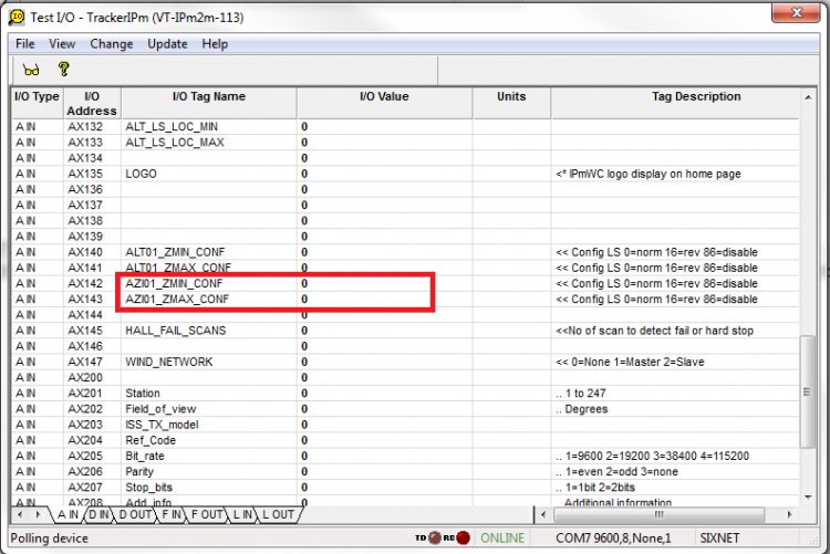
Configuration for Azimuth Motor
Open the Test I/O window. Under the A IN tab, locate the following transfers (AX142 and AX 143)
- AZ01_ZMIN_CONF changes the configuration for the minimum limit switch on the azimuth motor. Input 0 for normally open, 16 to reverse to normally closed, and 86 to disable
- AZ01_ZMAX_CONF changes the configuration for the maximum limit switch on the azimuth motor. Input 0 for normally open, 16 to reverse to normally closed, and 86 to disable
Azimuth limit and deadband
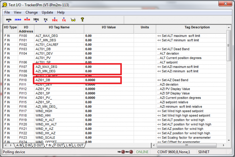
Next go to the F IN tab and locate the following transfers
- AZI_MAX_DEG defines the soft limit maximum for azimuth adjustment, which uses the software to impose an upper limit on the motor movement for the azimuth motor
Azimuth limit and deadband (continued)
- AZI_MIN_DEG defines the soft limit minimum for azimuth adjustment, which uses the software to impose an lower limit on the motor movement for the azimuth motor
- AZI01_DB defines the dead band for the altitude motor control. Smaller dead band will adjust the motor position more often, and increase accuracy, but can also cause unnecessary wear on the motor.
Azimuth Motor position
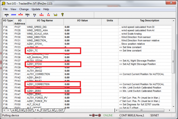
Next scroll down in the F IN tab to find the following transfers (FI134, FI138, FI144, FI146)
- AZ01_TC changes the time constant for the Azimuth motor
- AZ01_STOW changes the azimuth night stow position for the panel. A stow position of zero will cause the motor to remain in its last position at night. Any other degree input will cause the motor to stow at night in that position.
(continued)
- AZ01_CORRECTION allows the user to apply a correction to the azimuth position of the motor. If the tracker appears to be off from the sun, this can be used to correct it.
- AZ01_ZERO is the angle of the physical azimuth limit switch. When the tracker hits the limit switch it will use this value to re-calibrate its present position.
Azimuth Motor Pulses
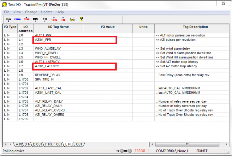
Changing the transfers squared in red will change the following:
- AZ01_PPR defines the number of pulses per revolution (360 degrees) for the azimuth motor. Some drivers will provide this number. It is important to note that the tracking hardware does not need to rotate 360 degrees for this number to be accurate
For example, take a Kinematic 3′ slew with a brush motor and the following specifications:
Motor pulses per full rotation — 2:1
Planetary Gear Ratio ———– 236:1
Worm Gear Ratio ————— 62:1
Total Pulses Per Rotation = (2)*(236)*(62) = 29,264
- AZ01_LATENCY is used to tune large trackers to prevent overshooting the desired position. This should be left at the default value of 100